Residential Addition/Remodel
INFORMATION BULLETIN
140
January 2025
This information bulletin describes the submittal requirements and permitting process for additions and remodels to single family dwelling and duplexes, not exceeding one story in height above grade or above crawl space. The information and sample drawings provided herein are suitable as a guide and cannot be used for construction. Project specific construction plans must be submitted for review.
Submittal Requirements
- Forms
Project Contacts Information Form
The Project Contacts Information Form (DS-345) must be submitted with all projects.
Owner-Builder Verification Form
The Owner-Builder Verification Form (DS-3042) is required if the property owner is acting as the general contractor. If you are not a licensed contractor and intend on performing the work yourself or hiring licensed subcontractors, an Owner-Builder Verification form must be completed and submitted with your project documents.
Water Meter Data Card
A Water Meter Data Card (DS-16) must be completed if new plumbing fixtures are being added. This form is not required when replacing or relocating existing fixtures.
Stormwater Requirements Applicability Checklist
Form DS-560 will be used to determine the storm water requirements for the project and is required for every plan submittal.
Plans and Specifications
Plans must be drawn to scale and be of sufficient clarity to indicate the location and extent of the proposed work. Existing and proposed construction and alterations to the existing home impacted by the addition should be clearly shown. Plans must show that all work conforms to the provisions of the current edition of the California Residential Code (CRC), the San Diego Municipal Code and all other relevant laws, ordinances and regulations applicable in the City of San Diego. Provide and show the following items, as applicable.
Site Plan and Vicinity Map
See Information Bulletin 122 for detailed information.
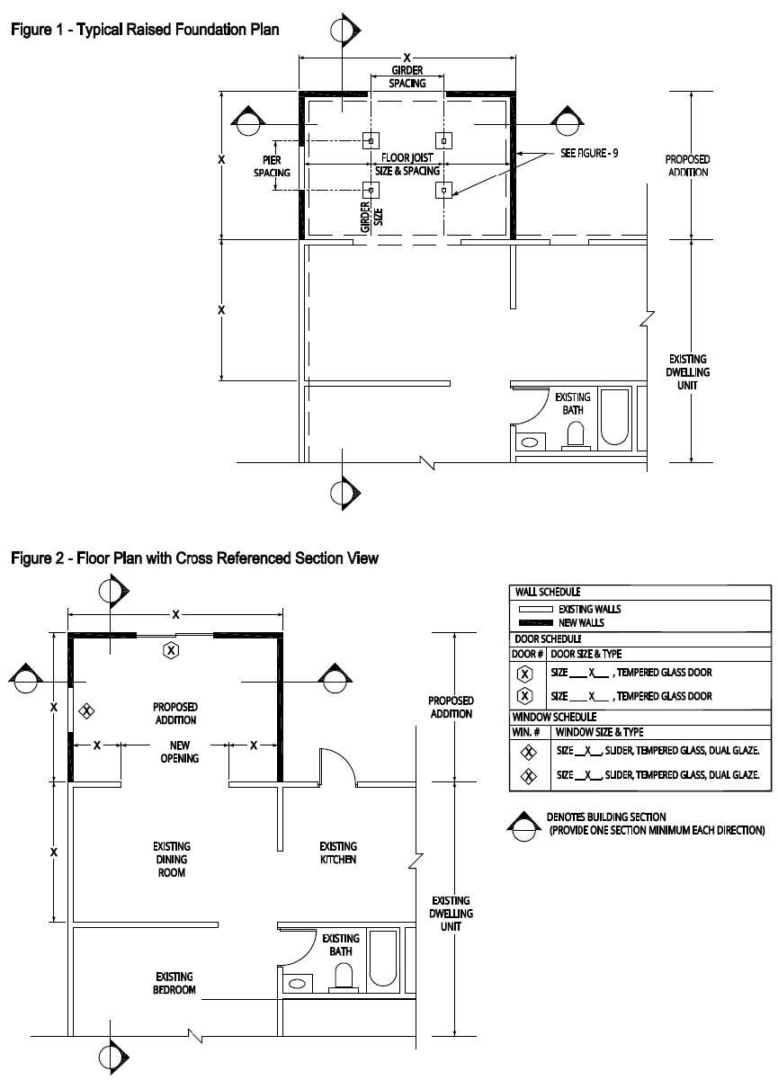
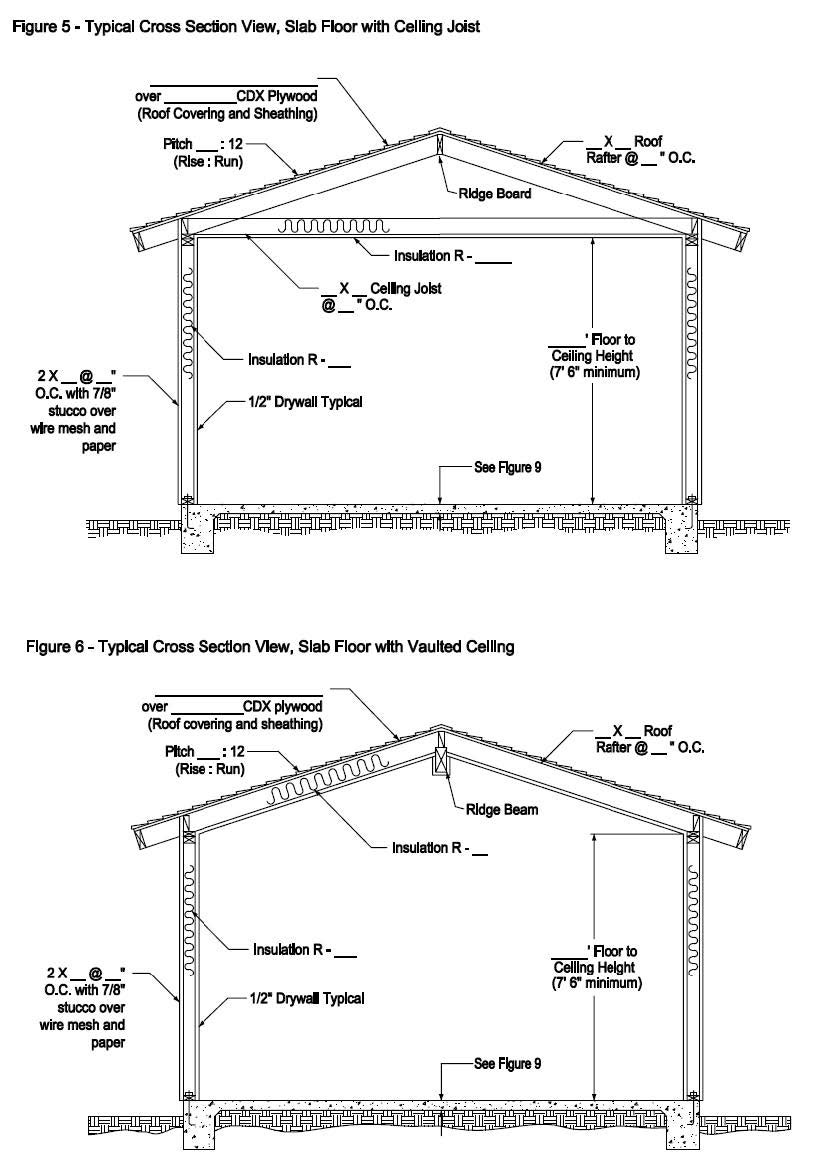
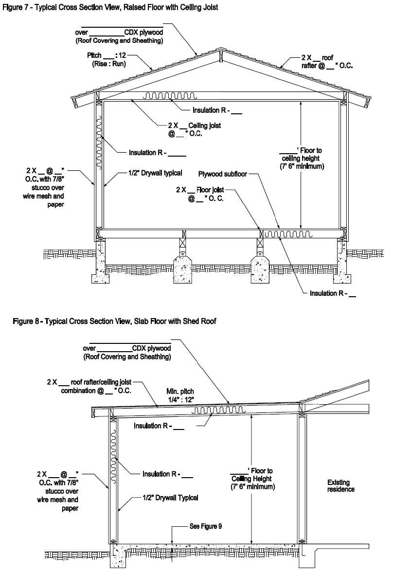
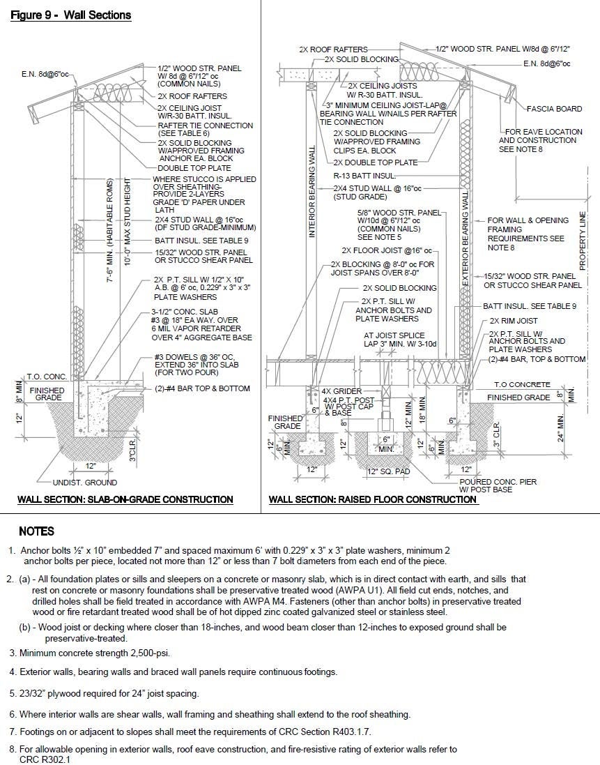
- Foundation (See Figure 1 & 5-9)
- Foundation Plan and Details (See Figure 1 & 5-9)
- Size, depth, and location of footings.
- Rebar size and spacing.
- Concrete compressive strength (minimum 2500 psi).
- Concrete slab thickness (min. 3.5 inches).
- . Raised Floor Construction
- Location of continuous foundations and pier footings.
- Size and depth of footings.
- Dimension of stem.
- Size and spacing of cantilevered joists (see Table 5).
- Size and spacing of floor joists (see Table 3).
- Location and size of crawl space access openings and vents (CRC R408).
- Foundation Plan and Details (See Figure 1 & 5-9)
- Floor Plan (See Figure 2)
- Identify use and dimensions of all existing and proposed rooms.
- Size and types of windows and doors.
- Location and type of all plumbing fixtures.
- Location and energy output (BTUs) of all heating equipment.
- Location and type of bathroom exhaust fan(s).
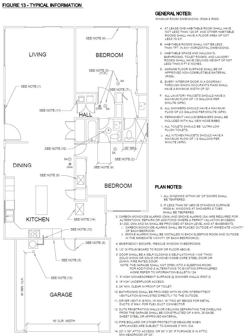
- Location and type of smoke and carbon monoxide alarms (see Figure 13).
- Attic access location.
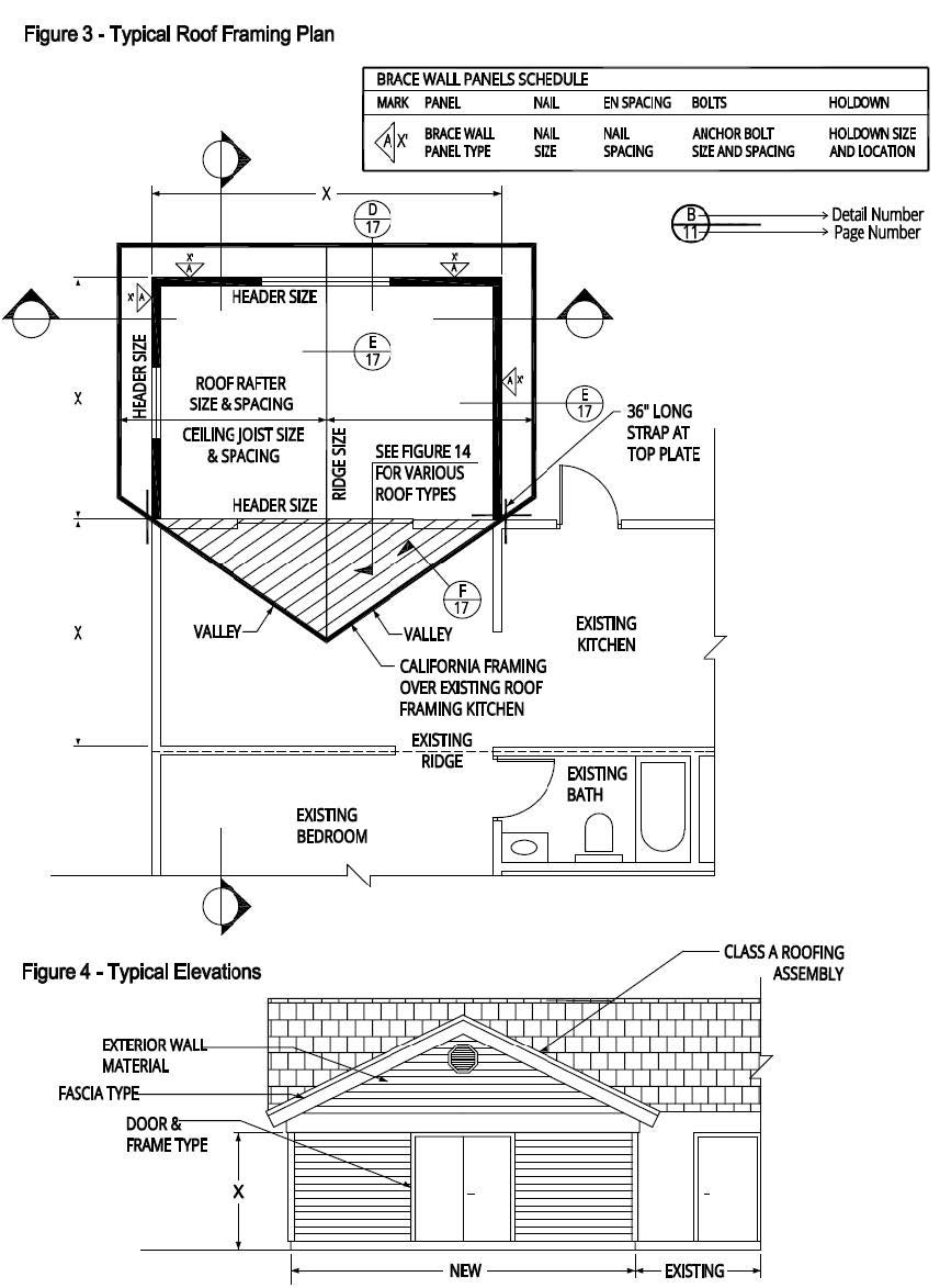
- Roof Framing Plan (See Figure 3)
- Size, spacing and span between supports for the existing roof framing impacted by the area of alteration.
- Size and spacing of all new rafters and ceiling joists (see Tables 1 and 2).
- Size of headers above wall openings and number of trimmer studs (see Table 4).
- Special framing around roof openings such as skylights and chimneys.
- Size and number of nails for rafter tie connection (see Table 6).
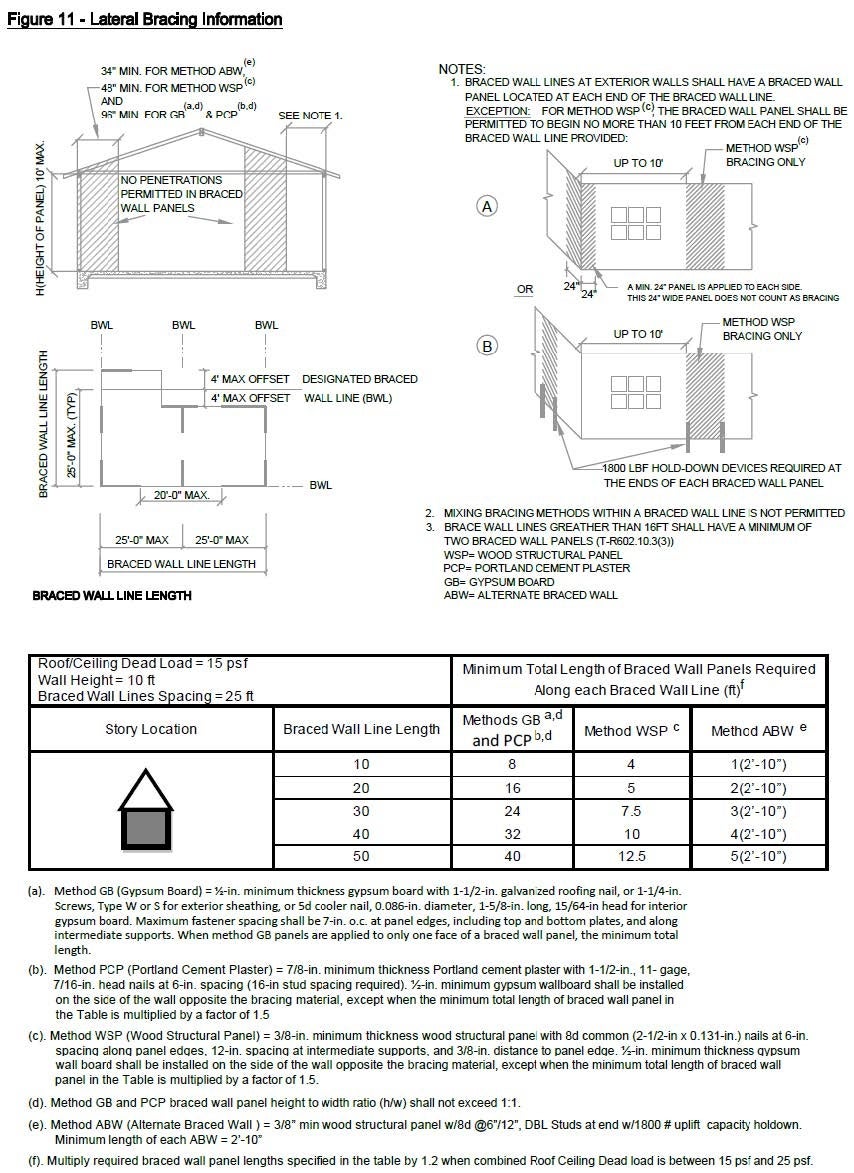
- Wall bracing, shear panels or other means of obtaining required lateral bracing (see Figure 11).
- Exterior Elevation Views (See Figure 4)
- Each exterior wall shown from the outside of the building and exterior finish of the walls and roof.
- Doors, windows and other openings.
Pre-existing and finished grade and building height to the most restrictive grade.
Note: Roof covering must be minimum Class “A”. Refer to Information Bulletin 123 for requirements concerning renewal of roof covering.
Connection Details
Sufficient details must be shown to clearly explain the method of construction and means of connection. Details should be referred on framing and foundation plans.
- Refer to Figures 5 through 8 for cross-section through addition.
- Refer to Figure 9 for exterior and interior load-bearing walls and foundation.
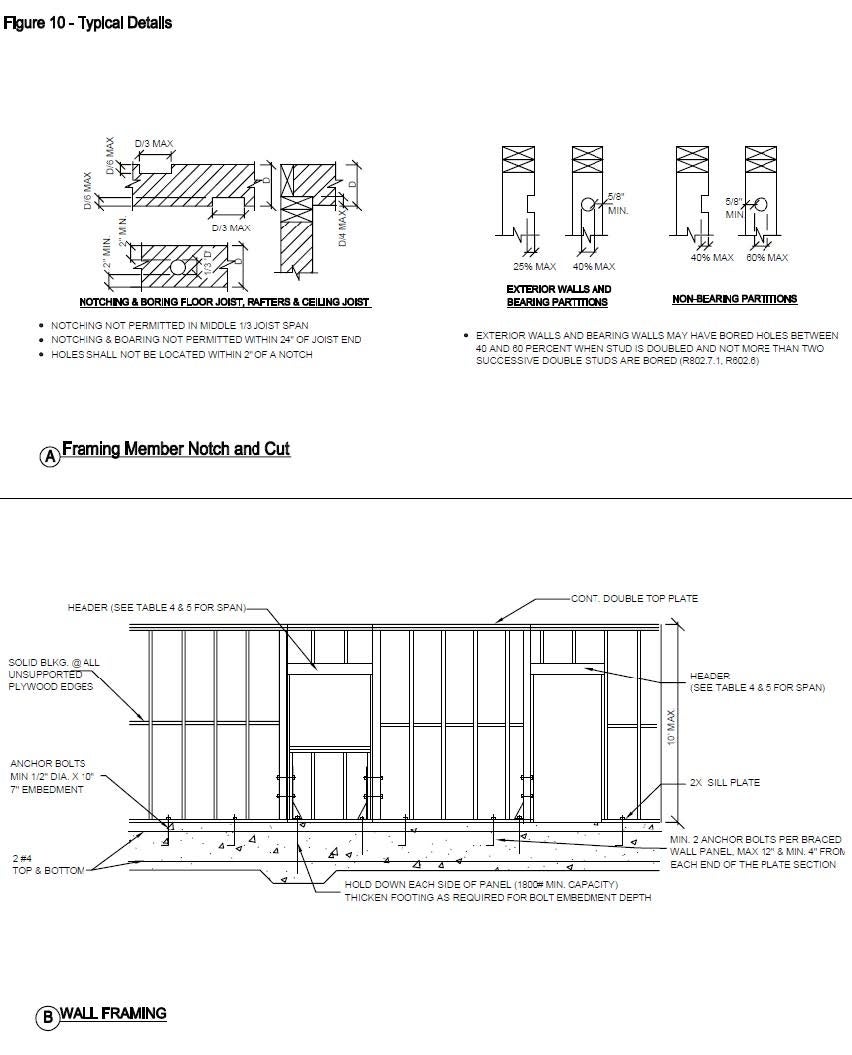
- Refer to Figures 10 and 11 for framing details.
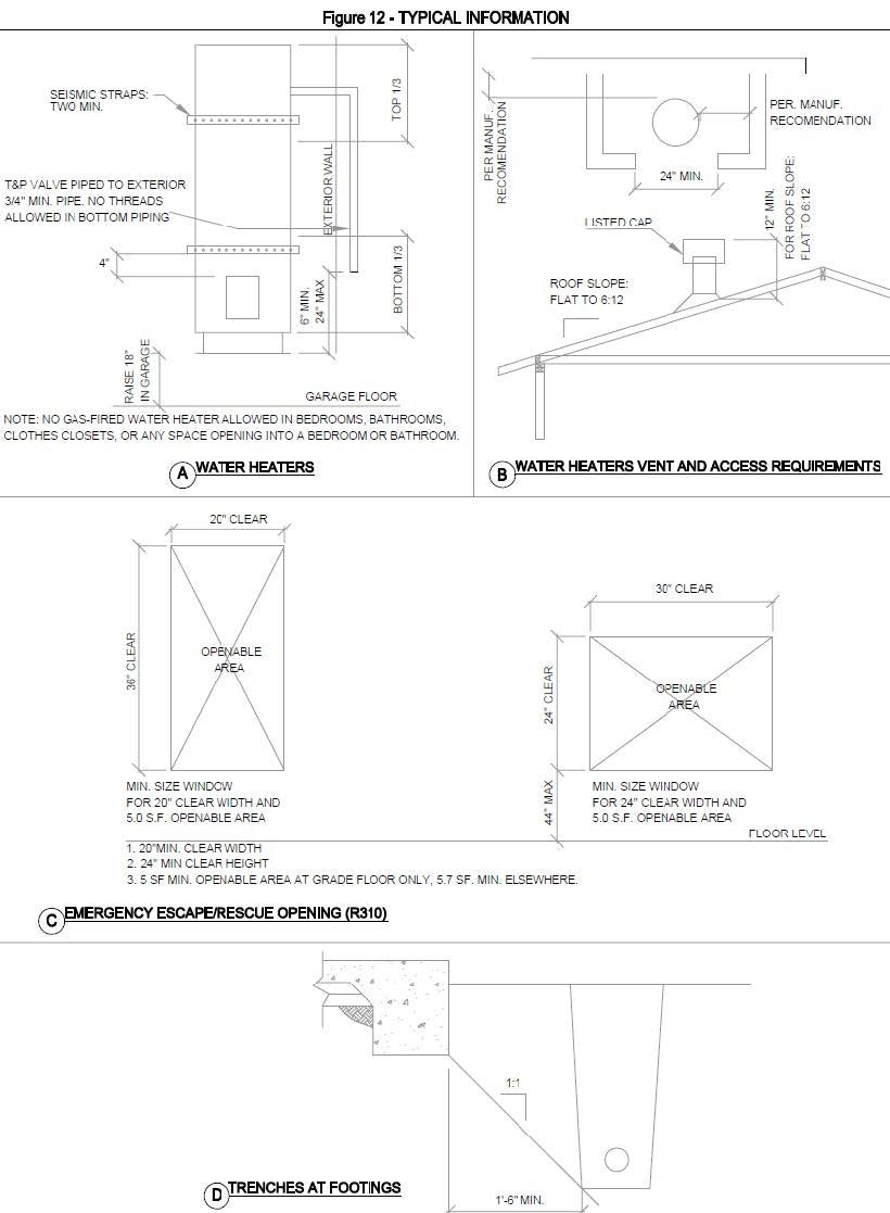
- Refer to Figure 12 for emergency escape windows in bedrooms, and seismic straps for water heaters.
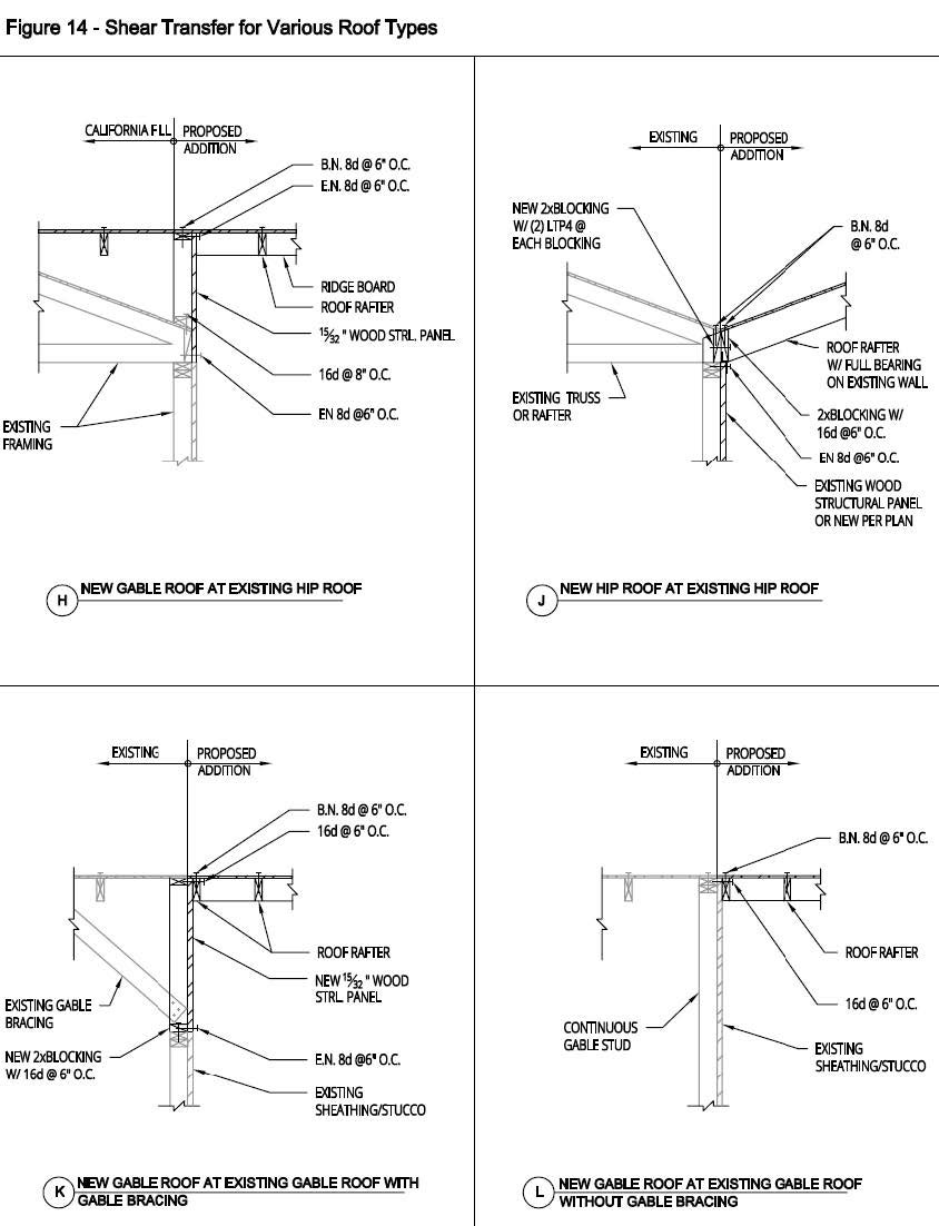
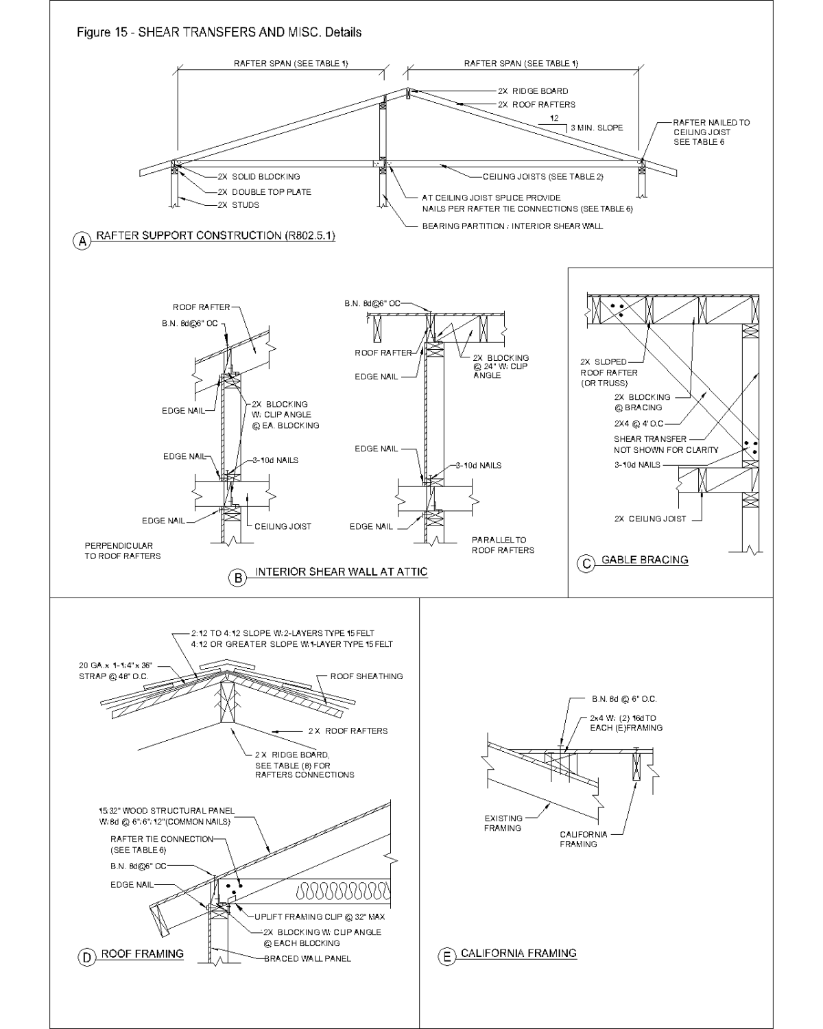
- Refer to Figures 14 and 15 for shear transfers and miscellaneous details.
Truss Calculations
If prefabricated trusses are included as part of the roof framing system, truss calculations stamped by a professional architect or registered civil engineer, licensed in the State of California must be provided. The truss calculations identification number must identify each truss type on the roof framing plan.
Site Soils Condition
A geotechnical investigation report must be provided for foundations placed on fill material or when placed on expansive soil. Add the following notes on plan when foundations are placed on undisturbed native soil:
- “The structure(s) will be located entirely on undisturbed native soil." Signature___________________________________ Owner/Licensed Engineer or Architect.
- "If the Building Inspector suspects fill, expansive soils or any geologic instability based upon observation of the foundation excavation, a soils or geological report, and resubmittal of plans to plan check to verify that report recommendations have been incorporated, may be required."
Statement of Special Inspection
Specify on plans that special inspection is required when epoxy or expansion anchors are used. When special inspection is required, add the following notes on the statement of special inspection:
- NOTICE TO THE AGENT/ARCHITECT or ENGINEER OF RECORD: By using this permitted construction drawings for construction/installation of the work specified herein, you agree to comply with the requirements of City of San Diego for special inspections, structural observations, construction material testing and off-site fabrication of building components, contained in the statement of special inspections and, as required by the California construction codes.
- NOTICE TO THE CONTRACTOR/BUILDER/INSTALLER/SUB-CONTRACTOR/OWNER-BUILDER: By using this permitted construction drawings for construction/installation of the work specified herein, you acknowledge and are aware of, the requirements contained in the statement of special inspections. You agree to comply with the requirements of City of San Diego for special inspections, structural observations, construction material testing and off-site fabrication of building components, contained in the statement of special inspections and, as required by the California construction codes.
- The special inspector must be registered by the City of San Diego Development Services Department, in the category of work required to have special inspection.
- The special inspections identified on plans are, in addition to, and not a substitute for, those inspections required to be performed by a City's building inspector.
Additional Regulations
Very High Fire Hazard Severity Zone (VHFHSZ)
When the addition and or alteration to an existing building is in a VHFHSZ and the building permit application for the existing building was deemed complete on or after 8/27/2009, the material and method of construction used for the addition and remodel shall comply with the requirements specified in CRC, Section R337, as amended by San Diego Municipal Code (SDMC) Section 55.9401.
Brush Management Zone
When the addition is encroaching or located within Brush Management Zones, it shall comply with the City of San Diego’s Landscape Regulations, SDMC Section 142.0412.
Storm Water Requirements & Best Management Practices (BMP’s)
The project shall comply with all requirements of the State MS4 permit; California Regional Water Quality Control Board (San Diego), the City of San Diego Land Development Code, and the City’s Storm Water Standards Manual.
- Construction BMP general notes: BMP notes are required on every plan set with a proposed ground disturbance of less than 1,000 square feet. The current notes may be found in the City’s Storm Water Standards Manual, Part 2, Appendix E.
- Water pollution control plan (WPCP) requirements:
- A WPCP is required for any project which has a ground disturbance that equals or exceeds 1,000 square feet but is less than 1 acre. A separate plan sheet must be included in the plan set which correlates to the WPCP.
- A Minor Water Pollution Control Plan (MWPCP), Form DS-570, may be utilized in lieu of a full WPCP for projects that create a ground disturbance of between 1,000 and 4,999 square feet and have less than a 5-foot elevation differential over the project area. If the project qualifies for an MWPCP, please fill out Form DS-570 and scan into the plan set along with Form DS-560.
- Energy Requirements
Additions or Alterations
All single dwelling units and duplex additions or alterations must comply with the California Energy Code (CEC), Title 24, Part 6. Several compliance methods are described in the Residential Manual and are available in the California Energy Commission website or call 1-800-772-3300.
Minimum Acceptable Requirements
See Table 9 for the minimum acceptable requirements for the simplest method. In addition to the Mandatory Measures summary (MF-1R form) mentioned in Section IV C of CEC, you may complete the required Certificate of Compliance (CF-1R form) using the information in this table. Forms must be shown on the plans and stapling is not permitted. Table 9 is based on Climate Zone 7. Some areas of San Diego are in Climate Zone 10.
Fenestrations
Manufactured fenestration (glazing) products must be labeled with certified U-factor, SHGC and infiltration certification. The rough opening and U- factor of all windows and doors with glass must also be noted on the plans (2022 Residential Compliance Manual 3.5).
Luminaries
All luminaries installed in residential construction must qualify as “high efficacy luminaires” which, apply to all indoor and outdoor lighting attached to single family buildings (2022 Energy Standards 6.1).
Electrical
Electrical drawings are not required for single family or duplex residential projects. The electrical system must be installed per the current edition of the California Electric Code and compliance will be verified at the time of inspection. See Figure 13 for location of smoke and carbon monoxide alarms and for exhaust fan requirements in bathrooms.
Plumbing
Plumbing fixtures shall be shown on the floor plan. Piping material must also be noted on the plans. All new plumbing fixtures must comply with the California Plumbing Code and the California Green Building Standards Code.
Zoning and Planning
The following regulations typically apply to residential additions and alterations.
Please consult the City of San Diego’s Municipal Code for all zoning regulations that may apply to your project.
Regulations SDMC Section Residential Base Zones……………………………………………………….131.0401
Planed Districts…………………………………………………………………..151.0101
Brush Management…………………………………………………………...142.0403
Landscape………………………………………………………………………….142.0401
Environmentally Sensitive Lands………………………………………..143.0101
Parking……………………………………………………………………………….142.0501
Overlay Zones…………………………………………………………………….132.0101
- Historic Review
Historical Review - Designated Historic
If the project involves any parcel containing designated historical resource, or is located within the boundaries of an adopted historic district, plans will be required and shall be submitted for Historical Review. Please refer to Information Bulletin 581, Designated Historical Resource Review for additional Historic Review information.
Historical Review - Potential Historic Resource
If the site contains buildings or structures 45 years old or older, and the scope includes any exterior work (except in-kind roof repair and replacement), plans and other information will be required and shall be submitted for Historical Review. (For other potential historic review exemptions, see Municipal Code Section 143.0212). See Information Bulletin 580, Potential Historical Resource Review for supplemental submittal requirements
Fire Sprinklers
For fire sprinkler requirements, refer to Information Bulletin 124, How to Obtain a Permit for Residential Fire Sprinklers.
Options for Service
Plans for residential addition/remodel requires a building permit and must be submitted electronically through the online portal by selecting Building Permit.
Project Fees
The plan check fees are required to be paid prior to review. For your convenience, DSD offers online payments. Payment may also be made in person by cash, check, debit card, Visa or MasterCard credit cards. Checks shall be in the exact amount, drawn on US banks, and made payable to the “City Treasurer.”
Refer to Information Bulletin 501, Fee Schedule, Construction Permits - Structures for applicable fees. Please note that plan check fees and other administrative fees are non-refundable.
See Refund Policy noted within Refund Application Form DS-721 for additional refund information.
Inspections
For inspection requirements, refer to Information Bulletin 120.
References
- San Diego Municipal Code (SDMC)
- 2022 California Residential Code (CRC)
- Circuit Card, DS-1779
Inspection Record Card, DS 1798
- “Minor” Water Pollution Control Plan (MWPCP), DS-570
- San Diego Standard Drawings
Tables & Figures
Table 1 | Table 2 | Table 3 | ||||||
ALLOWABLE SPANS FOR DF #2 ROOF RAFTERS (DF-LARCH) Dead Load: up to 10/20 (Shingles/Tiles) psf Total (Including roofing) Live Load: 20 psf, L/∆ = 240, (T-R802.4.1(2)) | ALLOWABLE SPANS FOR DF #2 CEILING JOIST (DF-LARCH) | ALLOWABLE SPANS FOR DF #2 FLOOR JOIST (DF-LARCH) | ||||||
RAFTER SIZE | SPACING | ALLOWABLE SPAN (SHINGLES / TILES) | JOIST SIZE | SPACING | ALLOWABLE SPAN | JOIST SIZE | SPACING | ALLOWABLE SPAN |
2X6 | 24” 16” 12” | 11’-11” / 10’-4” 14’-1” / 12’-7” 15’-6” / 14’-7” | 2X4 | 24” 16” 12” | 7’-3” 8’-11” 9’-10” | 2X6 | 24” 16” 12” | 8’-3” 9’-9” 10’-9 |
2X8 | 24” 16” 12” | 15’-1” / 13’-0” 18’-5” / 16’-0” 20’-5” / 18’-5” | 2X6 | 24” 16” 12 | 10’-8” 13’-0” 15’-0” | 2X8 | 24” 16” 12” | 10’-5” 12’-9” 14’-2” |
2X10 | 24” 16” 12” | 18’-5” / 15’-11” 22’-6” / 19’-6” 26’-0” / 22’-6” | 2X8 | 24” 16” 12” | 13’-6” 16’-6” 19’-1” | 2X10 | 24” 16” 12” | 12’-9” 15’-7” 18’-0” |
2X12 | 24” 16” 12” | 21’-4” / 18’-6” 26’-0” / 22’-7” 26’-0” / 26’-0” | 2X10 | 24” 16” 12” | 16’-5” 20’-2” 23’-3” | 2X12 | 24” 16” 12” | 14’-9” 18’-1” 20’-11” |
Table 4 | ||||||
ALLOWABLE SPANS (BRACED/UNBRACEDc ) FOR DF #2 ROOF BEAMS AND HEADERS FOR EXTERIOR & INTERIOR BEARING WALLS (DF-LARCH) Max. Dead Load: 20 psf, Max Live Load:20 psf, (T-R 602.7(1)) | ||||||
SIZE | 12-ft Building Widtha,d | NTb | 24-ft Building Widtha,d | NTb | 36-ft Building Widtha,d | NTb |
2-2x6 | 6’-0”/ 4’-3” | 1 | 4’-7”/ 3’-2” | 1 | 3’-10”/ 2’-8” | 1 |
2-2x8 | 7’-7”/ 5’-4” | 1 | 5’-9”/ 4’-0” | 2 | 4’-10”/ 3’-4” | 2 |
2-2x10 | 9’-0”/ 6’-9” | 1 | 6’-10”/ 4’-9” | 2 | 5’-9”/ 4’-4” | 2 |
2-2x12 | 10’-7”/ 7’-5” | 2 | 8’-1”/ 5’-8” | 2 | 6’-10”/ 4-9” | 2 |
3-2x8 | 9’-5”/ 6’-7” | 1 | 7’-3”/ 5’-1” | 1 | 6’-1”/ 4’-3” | 2 |
3-2x10 | 11’-3”/ 7’-10” | 2 | 8’-7”/ 6’-2” | 2 | 7’-3”/ 5’-1” | 2 |
3-2x12 | 13’-2”/ 9’-3” | 2 | 10’-8”/ 7’-1” | 2 | 8’-6”/ 6’-0” | 2 |
4-2x8 | 10’-11”/ 7’-8” | 2 | 8’-4”/ 5’-10” | 1 | 7’-0”/ 5’-0” | 2 |
4-2x10 | 12’-11”/ 9’-0” | 2 | 9’-11”/ 7’-0” | 2 | 8’-4”/ 5’-10” | 2 |
4-2x12 | 15’-3”/10’-8” | 2 | 11’-8”/ 8’-2” | 2 | 9’-10”/ 6’-9” | 2 |
a. Building width is perpendicular to ridge measured to exterior walls.
b. NT – Number of trimmer studs required to support each end of header.
c. Braced condition: Roof plywood sheathing or rafters must directly bear and be nailed to beam or header.
d. Allowable span of braced beam / Allowable span of unbraced beam.
Table 5 | |||
CANTILEVER SPANS FOR FLOOR JOISTSa,b | |||
SIZE (Douglas fir-larch #2) | SPACING | CANTILEVER SPAN | UPLIFT FORCE (lbs)c |
2x8 | 12” | 34” | 165 |
2x8 | 16” | 29” | 180 |
2x10 | 12” | 49” | 201 |
2x10 | 16” | 42” | 220 |
2x10 | 24” | 34” | 255 |
2x12 | 16” | 57” | 268 |
2x12 | 24” | 47” | 330 |
a. Ratio of backspan to cantilever span shall be not less than 2:1.
b. A full-depth floor joist shall be provided at the cantilevered ends. Solid blocking shall be provided
between joists over the support.
c. Connection angle capable of resisting the indicated uplift force shall be provided at the backspan support.
Table 6 | |||||
RAFTER HEEL CONNECTION TO CEILING JOIST - ROOF LIVE LOAD 20 psf [Table R802.5.2(1)] | |||||
Rafter | Tie | Roof Span (ft) | |||
12 | 20 | 28 | 36 | ||
3:12 | 16 | 5 | 8 | 10 | 13 |
24 | 7 | 11 | 15 | 19 | |
4:12 | 16 | 4 | 6 | 8 | 10 |
24 | 5 | 8 | 12 | 15 | |
5:12 | 16 | 3 | 5 | 6 | 8 |
24 | 4 | 7 | 9 | 12 | |
1. When nails are clinched, nailing may be reduced by 25 percent.
2. Roof span is measured between exterior walls
Table 7 | ||||||
| ALLOWABLE SPANS AND LOADS FOR WOOD STRUCTURAL PANEL, FLOOR & ROOF SHEAT-ING CONTINUOUS OVER TWO OR MORE SPANS WITH STRENGTH AXIS PERPENDICULAR TO SUPPORTS: APPLIES TO PANELS 24” OR WIDER (T-R503.2.1.1(1)) | ||||||
SHEATING GRADE-STRUCT-1 | ROOF | FLOOR | ||||
PANEL SPAN RATING | MINIMUM PANEL | MAXIMUM SPAN (INCHES) | LOADS (PSF) | MAX. SPAN (INCHES) Panel edges with tongue and groove joints or with blocking | ||
EDGE SUPPORT | NO EDGE SUPPORT | TOTAL LOAD | LIVE LOAD | |||
24/0 | 3/8 | 24 | 20 | 40 | 30 | |
24/16 | 7/16 | 24 | 24 | 50 | 40 | 16 |
32/16 | 15/32, 1/2 | 32 | 28 | 40 | 30 | 16 |
40/20 | 19/32, 5/8 | 40 | 32 | 40 | 30 | 20 |
48/24 | 23/32, 3/4 | 48 | 36 | 45 | 35 | 24 |
Table 8-Nailing Schedule | ||
CONNECTION (T-R602.3(1)) | FASTENING | REMARKS |
ROOF | ||
Blocking between joists or rafters to top plate | 3-8d (2-1/2” x 0.113”) | Toe nail |
Ceiling joist to plate | 3-8d (2-1/2” x 0.113”) | Toe nail |
Ceiling Joist not attached to parallel rafter, laps over partitions | 4-10d (3” x 0.128”) | Toe nail |
Collar tie rafter, face nail or 20-gage ridge strap | 3-10d (3” x 0.128”) | Face nail |
Rafter to plate | 2-16d (3-1/2” x 0.135”) | Toe nail |
Roof rafters to ridge, valley or hip rafters: | 4-16d (3-1/1” x 0.135”) | Toe nail |
WALL | ||
Built-up corner studs | 10d (3” x 0.128”) | 16” o.c. |
Built-up header two pieces with ½” spacer | 16d (3.5”x0.162”) | 16” o.c. along each edge |
Continued Header two pieces | 16d (3.5”x0.162) | 16” o.c. along each edge |
Continuous header to stud | 4-8d (2-1/2” x 0.113”) | Toe nail |
Double Studs | 16d (3.5”x0.128”) | 12” o.c. |
Double top plates | 10d (3” x 0.128”) | 12” o.c. Face nail |
Double top plates, minimum 24-inch offset of end joints, face nail in lapped area | 8-16d (3-1/1” x 0.135”) | Face nail |
Sole plate to joist or blocking | 16d (3-1/1” x 0.135”) | 12” o.c. Face nail |
Sole plate to joist or blocking at braced wall panels | 3-16d (3-1/1” x 0.135”) | 12” o.c. Face nail |
Stud to sole plate | 4-8d (2-1/2” x 0.113”) or | Toe nail |
Top or sole plate to stud | 3-16d (3-1/2 ”x 0.135”) | End nail |
Top plates, lap at corners and intersections | 3-10d (3” x 0.128”) | Face nail |
FLOOR | ||
Joist to sill or girder | 4-8d (2-1/2” x 0.113”) | Toe nail |
Rim joist to top plate (roof application also) | 8d (2-1/2” x 0.131”) | 6” o.c. Toe nail |
Built-up girders and beams, 2-inch lumber layers | 10d (3” x 0.128”) | Nail each layer as follows: 24” o.c. at top and bottoms and staggered. Two nails at |
Ledger strip supporting joists or rafters | 4-16d (3-1/2 ”x 0.135”) | At each joist or rafter |
Table 9-Title Energy Requirements-Prescriptive for Climate Zone 7 & 10 | |||
Insulation1: | |||
| Ceiling | Climate Zone 7 | R-30 | |
| Climate Zone 10 | R-38 for Option B, R-30 for Option C | ||
| Wall | Climate Zone 7 & 10 | R-13 + R8 Cont. | |
| Floor | Climate Zone 7 & 10 | R-19 | |
| Roof | Climate Zone 7 & 10 | Radiant barrier is required in new roof | |
Fenestration: | |||
| Type | Dual Pane | ||
| Maximum Sq.Ft. | 20% of FA* total & | UF 0.30 or lower | |
| 5% West Facing | SHGC 0.23 or lower | ||
Doors: | |||
| Type | |||
| No Glazing | UF .20 or lower | ||
| Glazing Door | Treated as fenestration | ||
1. All buildings shall comply with the Quality Insulation Installation (QII) requirements in TABLE 150.1-A or B.
*The area of any glass removed, as a direct result of the room addition, may be added to 20% total.
Previous Versions of this Information Bulletin
This section contains previous versions of this Information Bulletin by the last day they were effective.
- 2025-01-23|IB-140 "How To Obtain a Permit to Build a Residential Addition / Remodel"

